1. State machine (sm)
For create a state machine, press the “Add state machine” button in the simulation view menu, there a new tab will be created with the creation interface, this interface is divided in
- Left side: basic data and sm type
- Center: workspace for add and link states
- Right side: for add inputs and outputs
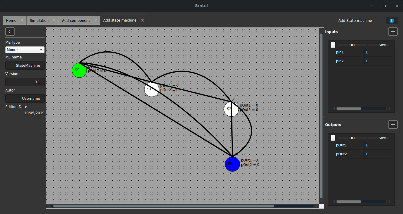
1.1. basic data
This is the information data of the state machine, the edition date is automatically updated.
Warning
Be careful with the name of the state machine, since it defines the files to be saved, if there is already a state machine with the name you enter, it will be replaced by the new machine.
1.2. Add I/O
For add an input or output, press the “Add” button located in the respective input or output section, two fields are automatically added to the table, these are
- ID: is the entry or exit identifier, must be unique
- Size: You can define a connector bus size
For delete a field, you must leave the ID field blank and press enter key.
1.3. Workspace
In this section, you can add states and join them for create a visual state machine. When you add a new state machine, there are two default states, the green state “SS” is the start state, and the blue state “FS” is the final state.
1.3.1. Add state
For add an state, you must press double click in a blank space of the workspace, there a circle identified with the state ID is created, which automatically increases
1.3.2. Delete state
For delete an state, you must select the state and press the Supr key.
1.3.3. Edit output in state
For add outputs to an state, the state machine must be moore type. Double click to state and a modal window will be displayed, there is a table, then you define the output value for all the outputs, this value is limited by
where Size is the bus size defined in the output addition
1.3.4. Join states
For join states, you must click on the source state and then click on the destination state, you will see that a line is created that joins them with an arrow identifying the origin and destination
1.3.5. Delete join
For delete a join, click in line and press supr key.
1.3.6. Edit conditions
The conditions are edited in the lines that connect the states, for this, double click in these lines, next a modal window is shown with two tabs
- Conditions tab: you can add the list of conditions, add a line with the button and modify them, if you have more open parentheses than closed ones, the program will automatically close them at the end
- Outputs tab: This section is enabled if the state machine is mealy type and its operation is the same as adding the outputs in the states.
1.4. Edit state machine
To edit a state machine, you must add a component of this state machine type to the simulation workspace, double click on the component and press the edit button located in the upper right part of the properties window.
When you add, edit or delete an input/output of a state machine, we recommend that you close Sintel and open for take the state machine changes.