2. Visual Interface
It has several interfaces throughout the software, among them are
- Home view
- Simulation view
- Settings view
- Add component view
- Add state machine view
2.1. Home view
When you start Sintel, the first view is the home view, this section is very basic, where you can create and open projects, there is a list of 3 recent opened projects ordered by accessed date.
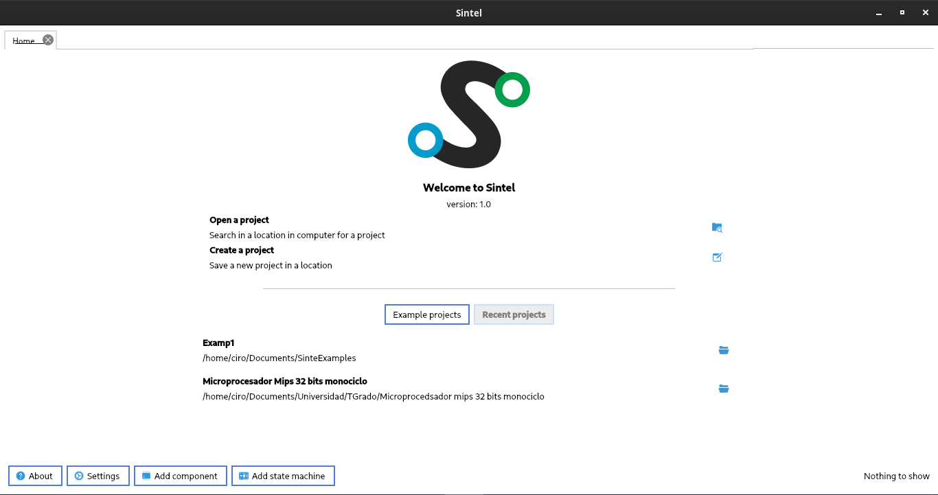
2.1.1. Open and load project
The projects extension is .sintel, you can open projects with this extension.
2.2. Simulation view
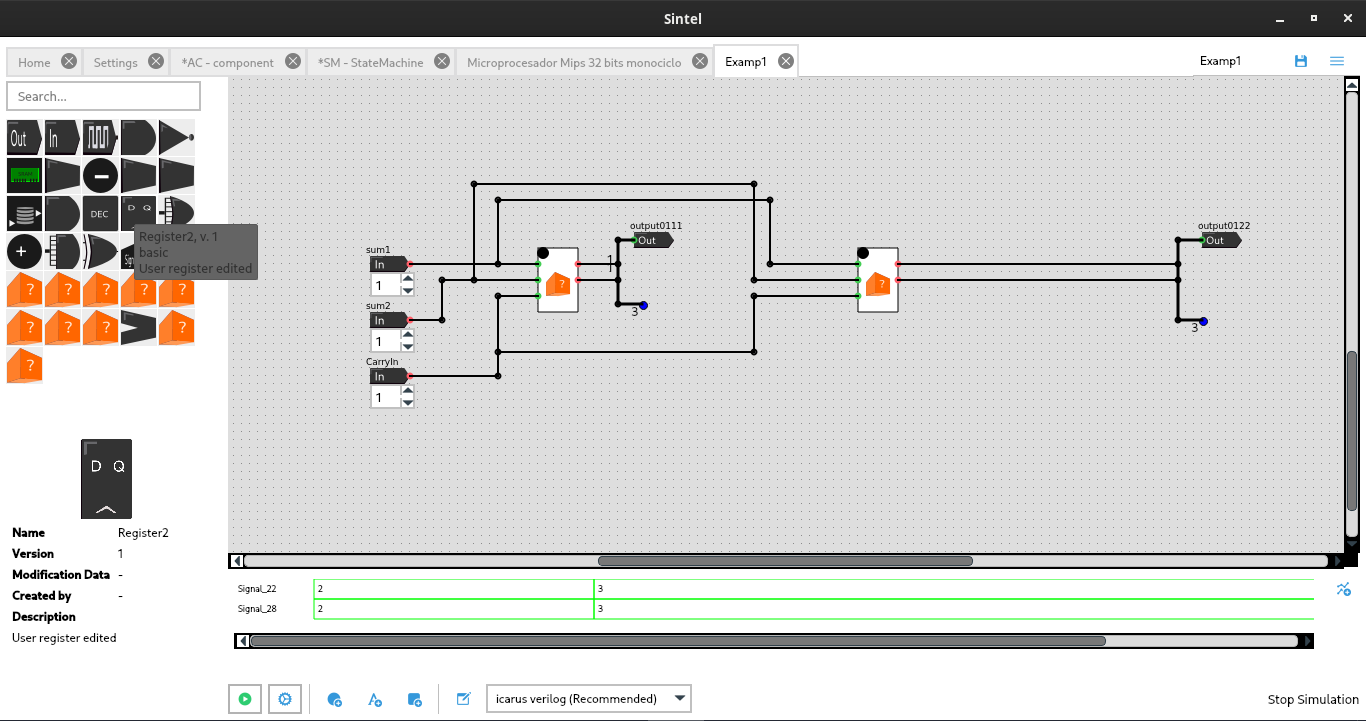
The simulation view is the main view in the software, since it’s the place where you can join components for simulate your digital system.
This section is displayed when you create or open a project. This view is divided in several parts like
- Left side: there is the components list, you can drag and drop them into the workspace
- Center side: there is the workspace, there you can join the components and model the digital system.
- Bottom side: there are several buttons, these buttons serve to run the simulation, and configure aspects of this.
- Top right side: there are buttons for save and open projects, and another button for open the simulation view menu.
- Simulation view menu: this menu has several options that will be described below.
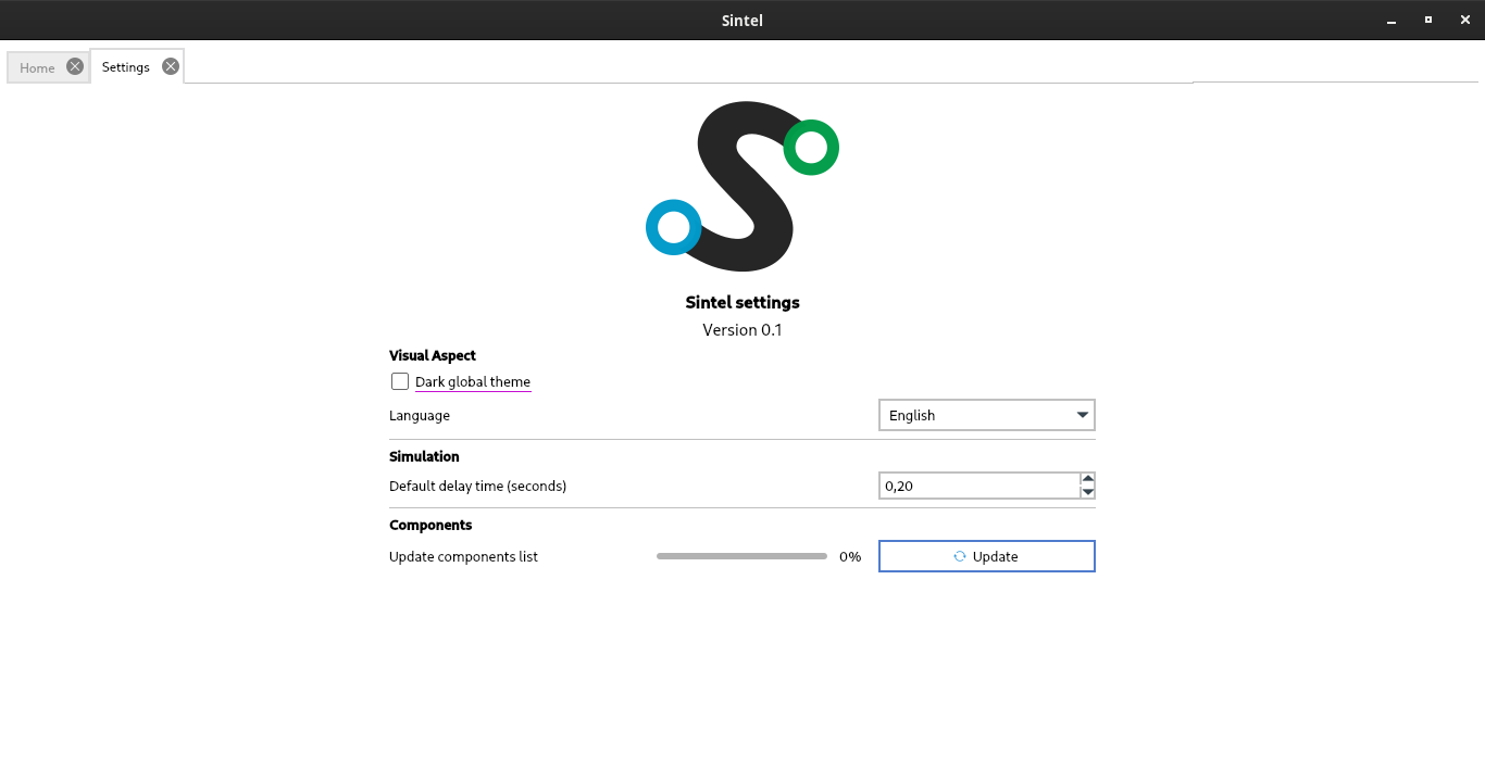
2.3. Settings view
This section is designed for select characteristics important for the experience in the software.
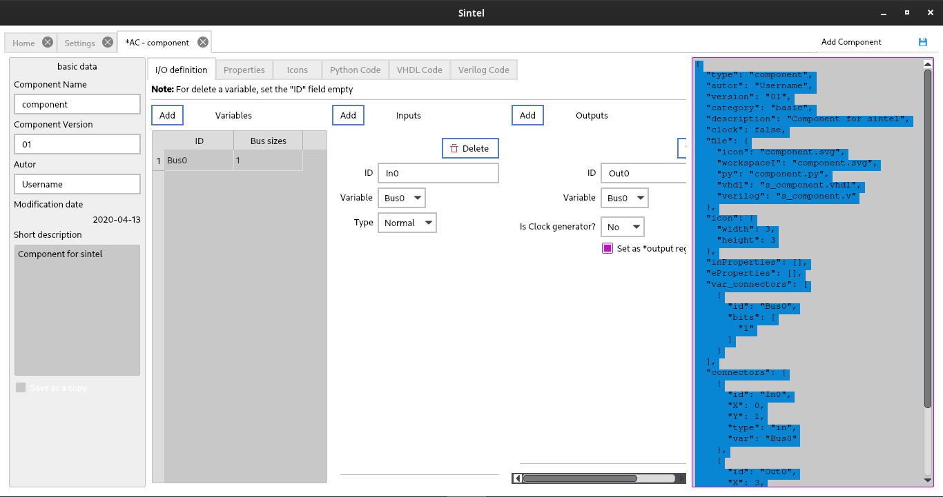
2.4. Add component view
This section is designed for give the possibilities of add new components from zero, adding i/o, code and icons.
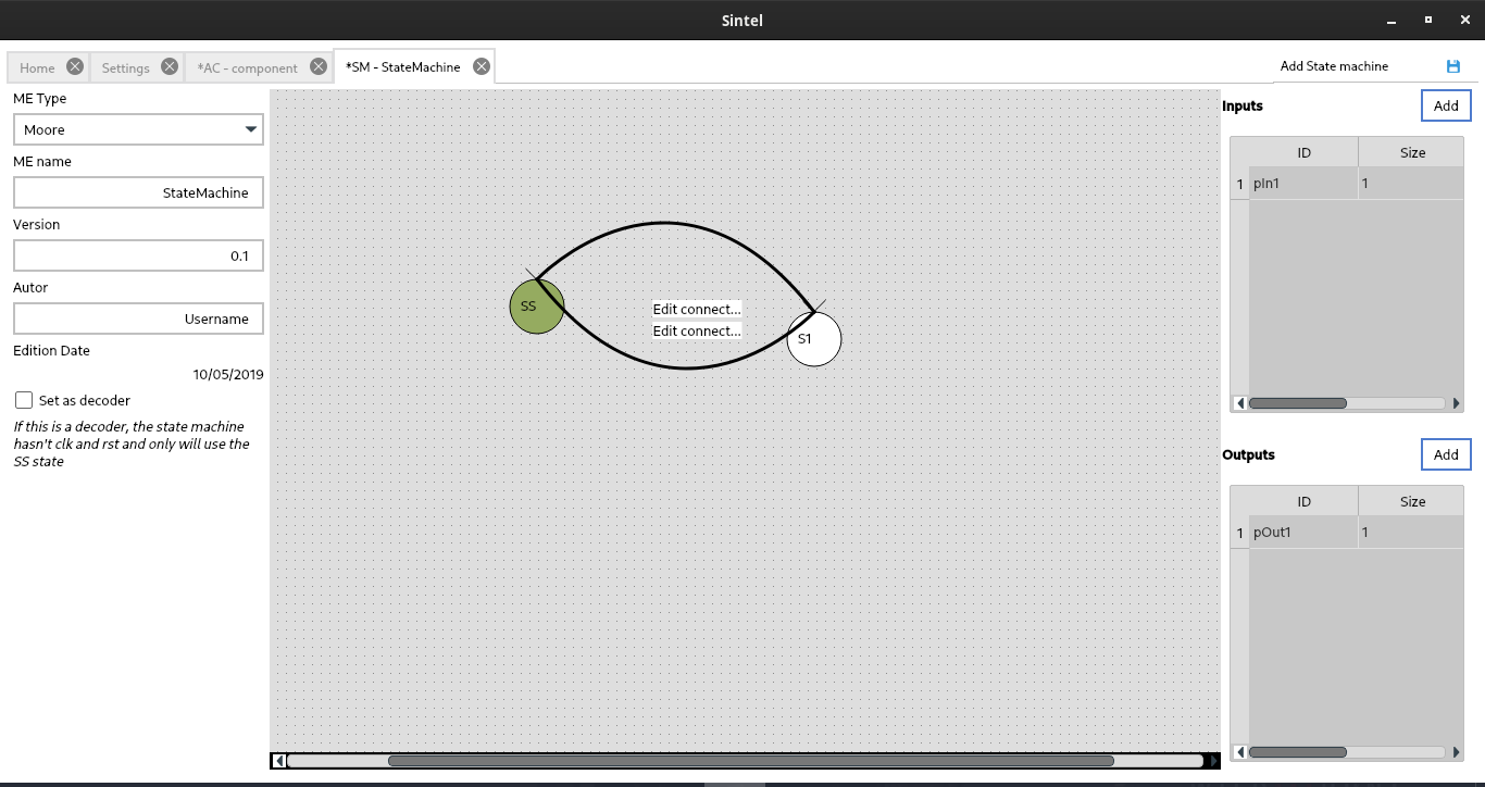
2.5. Add state machine view
In this view, you can add and edit a state machine graphically, for more information go to “Add state machine” section